In many industrial process systems, several valves must be operated in a specific sequence. Opening one valve before another reaches the correct position may create an unsafe condition, interrupt a process, cause equipment damage, or prevent maintenance work from being completed correctly. This is where mechanical interlocks become particularly useful.
But can one mechanical interlock control multiple valves?
The answer is yes, depending on the system design. A properly engineered mechanical interlock system can coordinate the operation of multiple valves and enforce a predetermined sequence. However, this does not usually mean that one simple locking device is physically attached to several valves at the same time. Instead, multiple mechanical interlock components can work together through a defined key-transfer or mechanical sequence.
This approach is commonly used in process piping, chemical processing, power generation, gas systems, water treatment, and other industrial applications where several valves must remain in specific positions during normal operation, isolation, startup, shutdown, or maintenance.
Understanding how multi-valve mechanical interlocks work is important for engineers, plant operators, and buyers looking for reliable industrial valve safety solutions.
Why Would Multiple Valves Need to Be Interlocked?
Industrial systems rarely operate with only one valve.
A process line may contain isolation valves, bypass valves, drain valves, vent valves, pressure-control valves, and equipment isolation valves. Their positions can be closely related to each other.
For example, a simplified process sequence might require:
-
Valve A to be closed.
-
Valve B to be opened.
-
Equipment to be isolated.
-
A drain valve to be opened.
-
Maintenance access to be permitted.
If operators can freely change the position of every valve, the intended sequence may depend entirely on procedures and human memory.
A mechanical valve interlock introduces a physical restriction into the system. Instead of relying only on instructions, the interlock can make certain operations impossible until the required previous step has been completed.
This is one of the major advantages of industrial mechanical interlocks: they provide physical sequence control.
How Can One Interlock System Control Multiple Valves?
When people ask whether one mechanical interlock can control multiple valves, it is important to distinguish between a single interlock device and a complete interlock system.
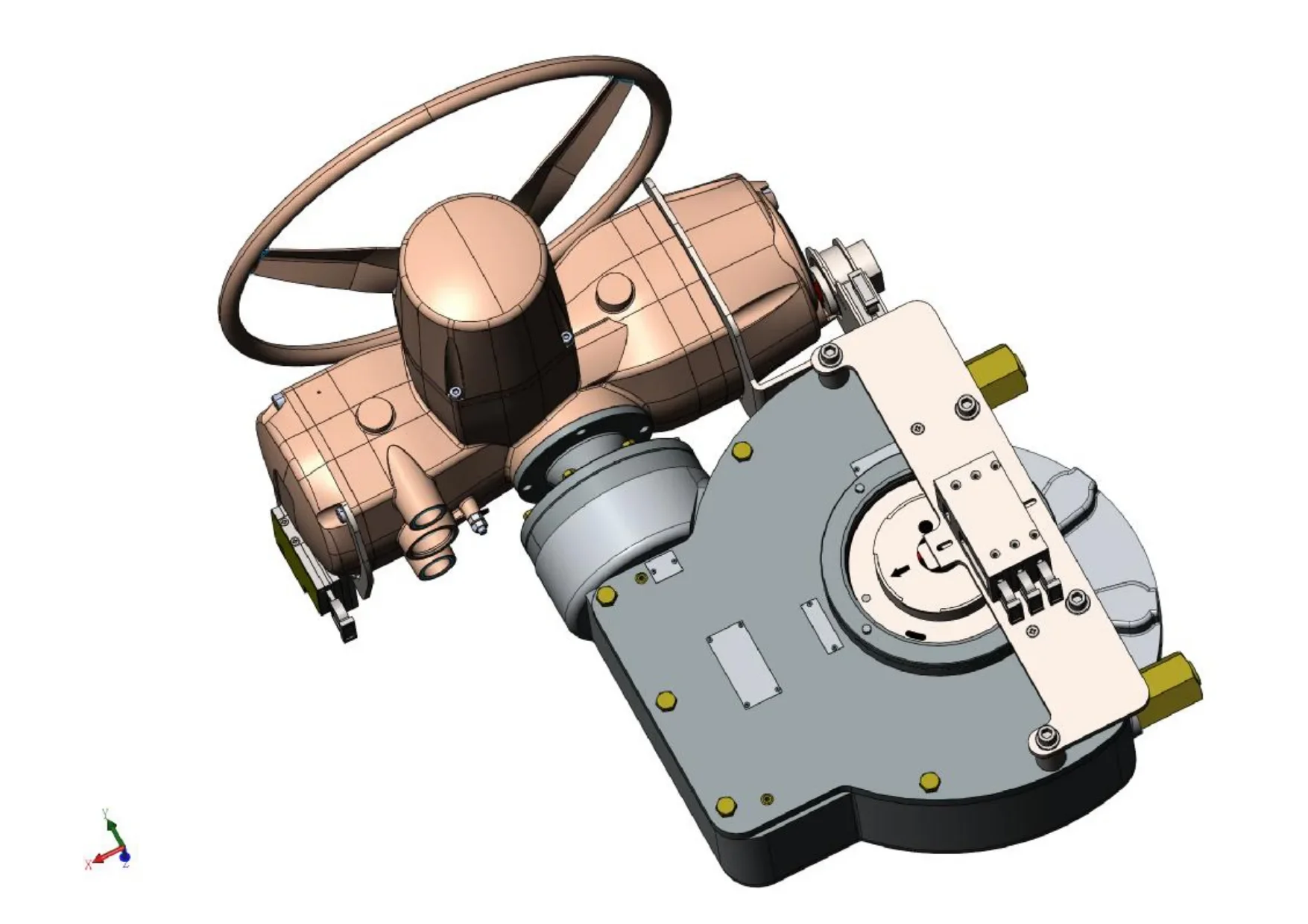
A single mechanical interlock mechanism is normally designed for a particular equipment interface. A multiple-valve application generally uses several interlock points connected through a key-transfer or mechanical logic arrangement.
In a trapped key interlock system, for example, a key may be trapped at one valve until that valve reaches the required position. Once the correct position is achieved, another key can be released. That key then allows the operator to proceed to the next valve.
The process can continue through several stages.
The result is a coordinated system in which multiple valves are controlled according to a predetermined sequence.
How a Multi-Valve Mechanical Interlock Works
Consider a simple system involving three valves: Valve A, Valve B, and Valve C.
The required operating sequence is:
Valve A → Valve B → Valve C
A mechanical interlock system can be designed so that the operator cannot proceed directly from Valve A to Valve C.
Step 1: Valve A
The operator operates Valve A to the required position.
When Valve A reaches the correct position, the corresponding interlock mechanism allows the designated key to be released.
Step 2: Valve B
The released key is transferred to the interlock associated with Valve B.
The key allows the operator to operate Valve B.
Once Valve B reaches its required position, another key can be released.
Step 3: Valve C
The next key is transferred to Valve C.
The operator can then complete the third operation.
This creates a physical sequence between the three valves.
The exact mechanism varies according to the application, but the basic principle remains the same: the ability to perform the next operation depends on completing the previous operation correctly.
Can More Than Three Valves Be Connected?
Yes.
Mechanical interlock systems can be designed for applications involving several valves. The number of valves is not necessarily the only factor determining complexity. The more important consideration is the required operating logic.
A system involving five valves may be relatively straightforward if the sequence is linear:
A → B → C → D → E
However, a system requiring alternative operating paths can be considerably more complicated.
For example:
A → B → C
or
A → D → E
may require different key-transfer arrangements depending on which process condition is selected.
This is why multi-valve mechanical interlock systems should be designed around the actual operating sequence rather than simply adding an interlock to each valve independently.
Linear and Complex Interlocking Sequences
Not every multi-valve application uses a simple one-direction sequence.
Linear Sequence
A linear sequence is the easiest to understand.
For example:
Valve 1 → Valve 2 → Valve 3 → Valve 4
Each operation releases the key required for the next operation.
This type of arrangement can be suitable for straightforward process isolation or startup procedures.
Sequential Isolation
A process may also require a sequence for safe isolation.
For example:
Close upstream valve → close downstream valve → open drain valve
The drain valve should not become available until the isolation valves are in the correct position.
Mechanical valve interlocks can help enforce this sequence.
Alternative Sequences
More complicated process systems may have several possible operating routes.
For example, a pipeline may have two alternative paths. The interlock system needs to prevent incompatible valve combinations while allowing the appropriate route to be selected.
These applications require more detailed engineering because the interlock logic must correspond to the process design.
Mechanical Interlocks for Multiple Isolation Valves
One of the most common reasons for using multi-valve mechanical interlocks is equipment isolation.
Suppose a pressure vessel is connected to several process lines. Before maintenance personnel can access the vessel, multiple valves may need to reach defined positions.
Simply closing one valve may not be enough.
A properly designed mechanical interlock system can require the relevant valves to be placed in their designated isolation positions before the next stage of the procedure becomes available.
This creates a physical relationship between valve positions and access or maintenance activities.
The same principle can be applied to pumps, compressors, process skids, heat exchangers, tanks, and other industrial equipment.
Multi-Valve Interlocks and Trapped Key Systems
Trapped key mechanical interlocks are particularly suitable for applications where multiple pieces of equipment must follow a controlled sequence.
The key itself becomes part of the operating logic.
A typical system may use:
-
Valve interlock units
-
Trapped key mechanisms
-
Transfer keys
-
Key exchange units
-
Access control locks
-
Equipment-specific locking devices
The key cannot be transferred until the required condition has been achieved.
This provides a physical method of controlling the sequence without relying entirely on electrical signals or operator judgment.
For complex industrial safety interlock systems, this can provide an additional layer of protection against incorrect operation.
What Determines the Number of Valves in an Interlock System?
There is no universal maximum number of valves that applies to every mechanical interlock system.
The practical limit depends on several factors.
Operating Logic
The first consideration is the actual process sequence.
A system with simple sequential logic may be easier to design than one with multiple branches and conditional operations.
Valve Configuration
Valve type, size, orientation, actuator configuration, and operating mechanism can affect the interlock design.
A mechanical interlock for a small manual valve may have very different requirements from an interlock designed for a large industrial valve with a high operating torque.
Physical Layout
The distance between valves can also affect the system.
If valves are installed far apart, a key-transfer system may be more practical than a direct mechanical linkage.
The physical location of each valve, access routes, equipment spacing, and operator working conditions should all be considered during design.
Environmental Conditions
Outdoor, corrosive, dusty, wet, or high-temperature environments can influence the choice of materials and components.
A multi-valve mechanical interlock installed in a chemical processing area may require different construction and protection from one used in a clean indoor environment.
Can One Mechanical Interlock Physically Lock Several Valves?
This depends on what is meant by "one mechanical interlock."
A single locking mechanism is generally intended to interact with a specific valve or equipment interface. It should not automatically be assumed that one device can physically connect and control several independent valves.
However, a mechanical interlock system can coordinate multiple valves.
This distinction is important when discussing projects with a mechanical interlock manufacturer or supplier.
Instead of simply asking for "one interlock for five valves," it is more useful to provide the complete sequence and explain what each valve must do.
The supplier can then determine the appropriate combination of mechanical interlock components and key-transfer mechanisms.
What Information Is Needed to Design a Multi-Valve Interlock?
A manufacturer will usually need more than just the number of valves.
Important information may include:
-
Valve type
-
Valve size
-
Valve manufacturer and model
-
Manual or actuated operation
-
Actuator type
-
Operating direction
-
Operating torque
-
Valve position requirements
-
Required operating sequence
-
Number of valves
-
Distance between valves
-
Installation environment
-
Available mounting space
-
Required key logic
-
Access requirements
-
Existing equipment limitations
A process diagram or valve schedule can also be extremely useful.
The more accurate the input information, the easier it is to develop a mechanical interlock solution that matches the actual installation.
How Multi-Valve Interlocks Reduce Operator Error
Human error remains an important consideration in industrial process operations.
Written procedures are necessary, but procedures alone do not physically prevent an operator from selecting the wrong valve or performing actions in the wrong order.
Mechanical interlocks provide another layer of control.
If the system is correctly designed, the operator cannot obtain the required key for the next operation until the previous condition has been satisfied.
This makes the correct procedure part of the physical equipment configuration.
It does not eliminate the need for operator training or written procedures. Instead, it supports those measures with physical control.
Mechanical Interlocks vs. Manual Operating Procedures
A manual procedure may state:
"Close Valve A before opening Valve B."
The operator must read and follow the instruction.
A mechanical interlock can be designed so that Valve B cannot be operated until the required condition at Valve A has been achieved.
This difference is significant.
The procedure communicates what should happen.
The mechanical interlock physically restricts what can happen.
For critical operating sequences, combining documented procedures with properly engineered mechanical interlocks can provide a stronger approach than relying on instructions alone.
Can Multi-Valve Interlocks Be Customized?
Yes. Custom mechanical interlock solutions are often required when standard products cannot match the equipment configuration or operating sequence.
Customization may involve:
-
Valve-specific mounting arrangements
-
Different key configurations
-
Special transfer sequences
-
Multiple operating stages
-
Special materials
-
Environmental protection
-
Existing equipment constraints
-
Non-standard valve arrangements
This is particularly relevant for large industrial projects where multiple valve types are installed across the same process system.
A mechanical interlock manufacturer with design and production capabilities can evaluate the actual valve configuration and develop a system around the required operating logic.
Common Challenges With Multi-Valve Mechanical Interlocks
Although multi-valve systems offer important advantages, they also introduce additional design considerations.
Incorrect Sequence Information
If the original process sequence is incomplete or incorrect, the interlock system may not reflect the actual operating requirements.
The process engineering team should therefore confirm the intended sequence before finalizing the interlock design.
Valve Modifications
If a valve, actuator, mounting arrangement, or piping configuration changes after the interlock is designed, the original interlock logic may no longer be appropriate.
Any major equipment modification should trigger a review.
Key Management
As the number of interlocked valves increases, key management becomes more important.
Keys should be clearly identified and managed according to the intended system logic. Confusion between keys can create operational problems.
Installation Accuracy
A multi-valve system may involve several interlock units installed at different locations.
Incorrect installation, poor alignment, or incomplete commissioning can affect system performance.
Installation and commissioning should therefore verify the complete operating sequence rather than testing each component in isolation.
How to Test a Multi-Valve Mechanical Interlock System
Testing should confirm that the complete sequence works as intended.
A typical verification process may include:
-
Confirm the starting condition of all valves.
-
Operate the first valve according to the approved sequence.
-
Verify that the correct key becomes available.
-
Attempt to perform an operation that should be prohibited.
-
Confirm that the prohibited operation cannot proceed.
-
Transfer the key to the next interlock.
-
Repeat the sequence for the remaining valves.
-
Verify the final operating condition.
-
Document the results.
The exact procedure should be established according to the system design, manufacturer's instructions, and applicable site requirements.
Final Considerations
So, can one mechanical interlock control multiple valves?
A single mechanical locking device is generally designed for a specific valve or equipment interface, but a properly engineered multi-valve mechanical interlock system can coordinate several valves through mechanical sequencing and trapped key technology.
The number of valves is only one part of the design. Operating logic, valve type, actuator configuration, physical layout, environmental conditions, key management, and the required safety sequence all influence the final solution.
For simple applications, a linear key-transfer sequence may be enough. More complex process systems may require customized interlocking logic to prevent incompatible valve positions and ensure that operators follow the intended sequence.
For buyers and engineers planning a multi-valve project, the most effective approach is to define the complete valve sequence first and then select the appropriate mechanical interlock configuration. With the right design, industrial mechanical interlocks can provide a practical physical layer of control for complex valve systems. Nudango can support customized mechanical interlock solutions for different valve configurations and industrial operating requirements, helping customers develop interlock systems that are designed around the actual equipment and sequence rather than relying on a one-size-fits-all approach.
www.nudango.com
nudango