Selecting the correct low-voltage busbar insulators for switchgear and panelboard assemblies is one of the most consequential decisions an electrical panel builder or switchgear OEM makes during the design verification phase. Under IEC 61439-1/2, the standard governing low-voltage switchgear and controlgear assemblies, every structural insulation component must be demonstrably capable of withstanding dielectric stress, thermal cycling, mechanical shock, and environmental pollution across the rated service life. Getting this specification wrong introduces flashover risk, mechanical failure during fault conditions, and potential non-compliance that invalidates the entire panel's Design Verification record.
This guide walks through the critical selection criteria — electrical, thermal, mechanical, and regulatory — that engineers and procurement specialists must evaluate when sourcing low-voltage standoff insulators for switchgear and panelboard applications.
Understanding the Core Electrical Requirements
The first parameter any specifier must verify is the Comparative Tracking Index (CTI). Tracking — the formation of carbonized conductive paths across an insulator surface — is the leading failure mechanism in industrial cabinets operating in Pollution Degree 3 environments. Under IEC 60664-1, which governs insulation coordination for low-voltage equipment, materials are classified into four groups based on CTI. Material Group I corresponds to a CTI of 600V or higher, offering the greatest resistance to conductive carbon tracking. Specifiers should demand Material Group I performance when insulators are exposed to condensation, dust, or industrial contaminants.
Dielectric withstand voltage is the second critical electrical parameter. For low-voltage switchgear rated up to 1,000V AC, insulators must survive a 3,500V AC (50Hz, 1-minute) proof voltage test without puncture or flashover. Beyond the continuous working voltage, surge resilience matters: IEC 60664-1 defines Overvoltage Category IV environments where insulators must withstand 1.2/50 μs impulse overvoltage up to 8kV. Any insulator shortlisted for IEC 61439-compliant assemblies should carry documented evidence of both tests.
Evaluating Thermal and Mechanical Performance
Busbar systems generate heat under continuous load, and switchgear located in outdoor equipment rooms or battery container environments experiences wide ambient swings. Specifiers must verify that candidate insulators maintain structural rigidity across the full operating temperature envelope. The Heat Deflection Temperature (HDT) under a 1.8 MPa flexural load is the relevant benchmark; materials that soften prematurely will allow busbars to shift under load, narrowing creepage distances and creating flashover conditions.
For applications in solar PV and battery energy storage systems, the thermal endurance requirement extends further. DC systems such as 1,500V DC battery racks and string inverter links impose continuous thermal loading and sometimes cyclic freezing. In these cases, insulators must remain functional from -40°C to +140°C to prevent embrittlement at the low end or structural softening at the upper limit.
Mechanical specification involves two distinct concerns. First, short-circuit electrodynamic forces: a fault event between parallel phase conductors generates repulsive electromagnetic forces that can fracture undersized supports or dislodge busbars from their spacing. Standards such as IEC 61439 require that supports withstand peak fault currents without mechanical failure; rated current capacities and short-circuit withstand values (expressed as Icw in kA/1s) must appear in the insulator's technical documentation. Second, insert pull-out and torsional resistance: threaded brass or steel inserts within the insulator body must resist the torque applied during busbar bolt-down. Documented tensile pull-out resistance values — for example, greater than 8,000 N for M8/M10 inserts — and torsional lock confirmation against bolt proof torque are non-negotiable data points for compliant Design Verification packages.
Compliance Pathways: Standards That Matter
Beyond IEC 61439-1/2, a fully compliant insulator specification intersects with several additional standards:
- IEC 60664-1: Insulation coordination — defines Overvoltage Categories and Pollution Degrees that determine minimum creepage and clearance distances.
- IEC 60273: Dimensions and requirements for hollow insulators applicable to post-type supports.
- IEC 60071: Insulation coordination for equipment — establishes the impulse voltage levels referenced in design verification testing.
- UL 94-V0: North American flammability classification requiring self-extinguishing performance, with an afterflame time of t1 + t2 no greater than 8 seconds and zero flaming drips, critical for enclosed switchgear where internal arc faults could ignite non-compliant plastics.
- RoHS 2011/65/EU & 2015/863 and REACH (EC 1907/2006): Environmental compliance requirements for European and North American market entry.
Panel builders who reference third-party SGS type test reports from their insulator supplier can often satisfy Design Verification documentation requirements under IEC 61439 without conducting independent destructive testing — a significant cost and schedule advantage.
Material Selection: BMC, SMC, and Epoxy Resin
Three composite material platforms dominate the low-voltage insulator market:
Bulk Molding Compound (BMC) and Dough Molding Compound (DMC) are thermoset composites offering isotropic mechanical properties, arc resistance, and precision mold shrinkage control. They are the standard choice for compact standoff insulators up to approximately 40 mm body diameter and are suitable for most low-voltage switchgear applications.
Sheet Molding Compound (SMC) uses longer glass fiber reinforcement — typically 25 mm to 50 mm — compared to BMC, delivering superior flexural and tensile strength. SMC is the preferred material for busbar support clamps and heavy-duty standoffs where short-circuit electrodynamic forces must be absorbed structurally.
Vacuum-cast epoxy resin, produced via automated pressure gelation (APG), provides a void-free monolithic structure. This matters for medium-voltage applications where internal partial discharge must be held below 5 pC at 1.1 Um, but it also appears in demanding low-voltage environments where volume resistivity requirements exceed 10¹⁴ Ω·cm.
Geometry, Threading, and Platform Compatibility
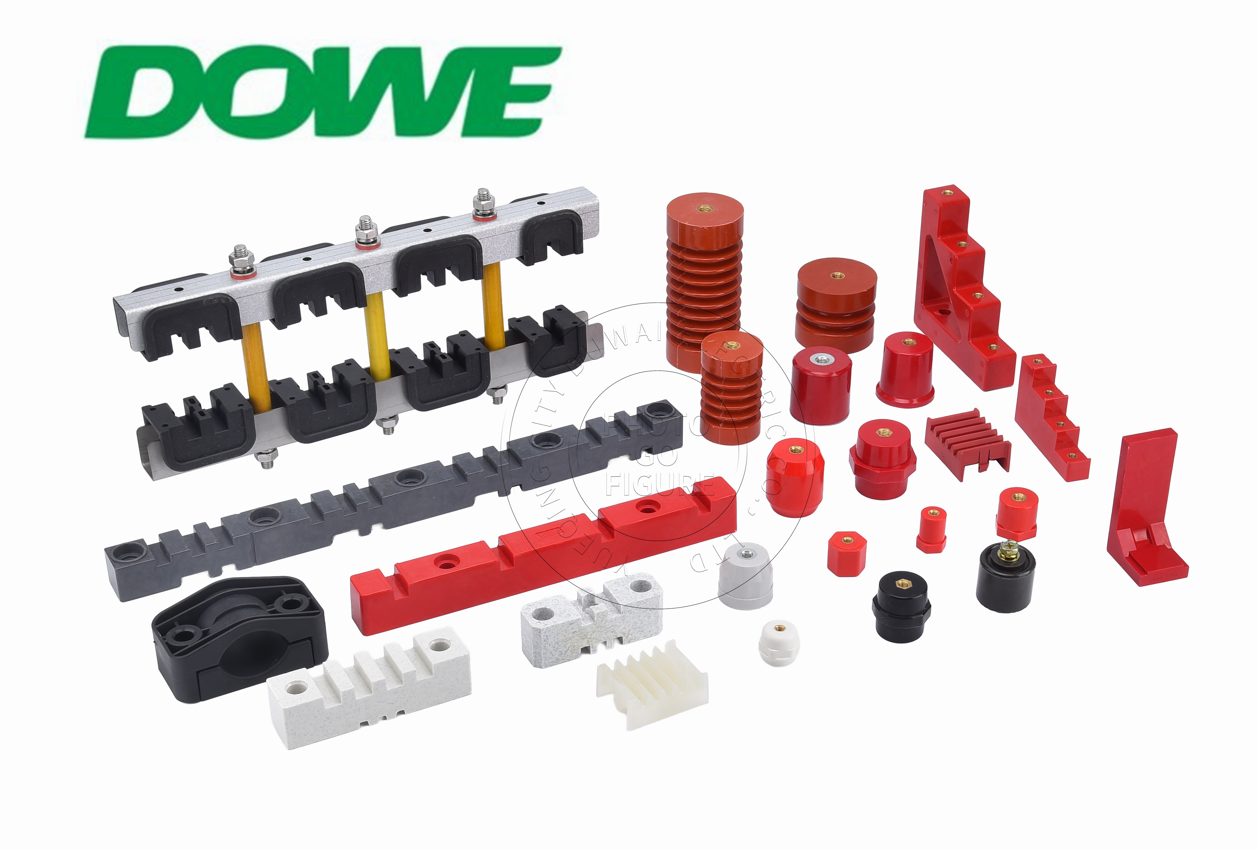
Insulator geometry determines both its mechanical function and its compatibility with the target switchgear platform. Ribbed conical profiles increase effective surface creepage path by 35% to 60% compared to a plain cylinder of the same height — without increasing vertical installation space. Hexagonal anti-rotation bases allow assembly technicians to hold the standoff with an open-end wrench while applying full tightening torque, preventing rotational shear stress on the mounting plate.
For replacement and retrofit projects on legacy cabinets — notably ABB MNS 2.0/3.0, Schneider Blokset and Okken, Siemens Sivacon, GE, and Eaton switchgear — dimensional precision is critical. A 1:1 drop-in OEM replacement that matches original mounting hole centers, busbar slot spacing, and creepage dimensions eliminates panel redesign costs entirely.
Thread sizing must match the mechanical load. Specifiers should map required tightening torque against published proof torque values: M6 through M8 threads cover most panelboard and low-current switchgear applications, while M10 through M16 threads are necessary for heavy-duty supports rated above 2,500A where bolt torque requirements increase substantially.
How DOWE Electric Addresses These Specification Requirements
DOWE Electric (also referenced commercially as DUWAI), headquartered in Yueqing, Zhejiang Province, China, has spent over two decades engineering insulation solutions specifically for global power distribution infrastructure. The company's product matrix spans low-voltage standoff insulators rated from 660V to 1,000V AC, busbar support and clamping systems rated up to 1,100V AC and 6,300A, and medium-voltage post insulators covering 3.6 kV to 12 kV AC.
Across its SM Series, SB/JYZ Series, EL Series, HC Heavy Duty, and XD3-D4 Series, DOWE Electric standardizes on CTI values of 600V or higher (Material Group I), UL 94-V0 self-extinguishing certification, and documented dielectric withstand performance of 3,500V AC for low-voltage products. The SB/JYZ Series in particular — available in body diameters from 14 mm (SB14) through 60 mm (SB60) with thread options from M5 through M16 — is engineered for high-voltage DC isolation up to 1,500V DC in solar PV, BESS, lithium battery, and EV charging applications, with thermal endurance from -40°C to +140°C.
For panel builders seeking compliant Design Verification documentation, DOWE Electric provides SGS third-party type test reports covering IEC 61439-1/2, IEC 60664-1, UL 94-V0, RoHS, and REACH compliance. The company's production capacity exceeds 500,000 low-voltage standoffs per month, and it exports millions of SB/JYZ insulators annually to solar inverter OEMs, battery pack integrators, and switchgear builders across Germany, the United States, Spain, Italy, the Netherlands, and Canada — serving more than 60 countries worldwide.
For OEM and ODM procurement teams managing legacy platform replacements, DOWE Electric's precision dimensional matching for ABB MNS, Schneider Blokset/Okken, Siemens Sivacon, GE, and Eaton switchgear offers a verifiable, standards-compliant alternative that removes the burden of independent destructive testing from the Design Verification process.
http://www.busbarinsulator.com
Yueqing City DUWAI Electric Co.,LTD